Post-Installed Anchor and Reinforcing Tensile Load Testing
By David Hampe, P.E., MSI, CWI
In the course of concrete construction, transitional reinforcing bars from one placement or building component into the next one can often end up being omitted, either through being missed in the process of concrete placement, or through an intentional decision to smooth-out construction sequencing. Alternately, it is possible that column anchor bolts get either misplaced or omitted. When this condition occurs, it is common industry practice to install these bars and anchors after concrete placement has occurred and the concrete has hardened, hence post-installed anchors.
The process itself is relatively simple. A hole is drilled into the hardened concrete 1/8” diameter wider than the bar or anchor (test member) to be installed, to a depth the structural engineer-of-record typically determines. This depth can range from up to 40 or more bar diameters for a lap splice, or the depth may be only a few inches if the test member is installed in a shallow concrete placement, such as in a concrete slab. The hole is thoroughly cleansed of water, concrete dust, and general debris. A structural epoxy is injected into the hole from the bottom up, and the test member is inserted into the full depth of the hole.
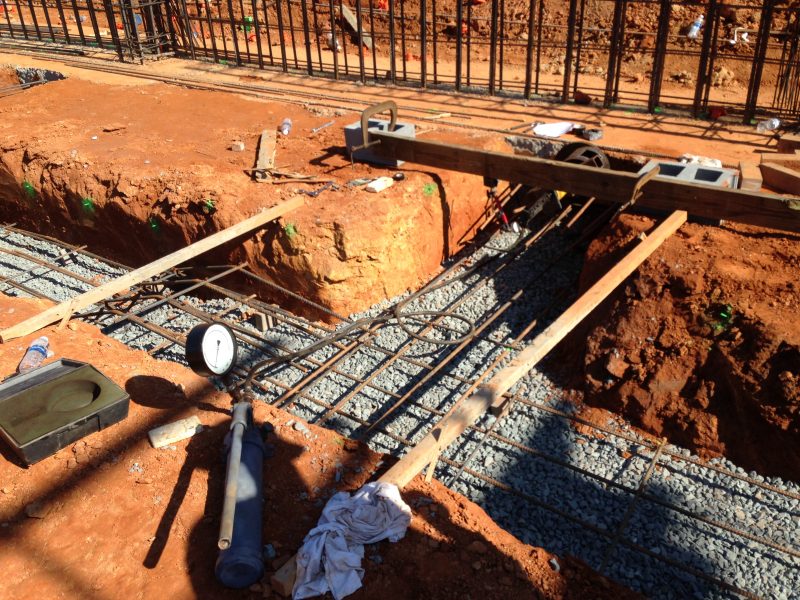
In some circumstances, the engineer-of-record may request the performance of a load test on the installed test members. To accomplish this test, a calibrated hydraulic jack is typically attached to the test member, and a tensile load is applied to the test member in increments up to the maximum test load the engineer-of-record specifies, possibly up to as much as 80% of the yield strength of the steel in the test member. A dial gauge or gauges are affixed to an independent anchor point to measure the axial deflection of the member being tested.
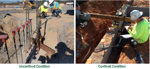
When looking at testing bars and anchors, two test conditions are considered: the unconfined condition and the confined condition. As the tensile load is applied to the test member, the stress forces on the member propagate upward toward the surface of the concrete, starting from the bottom of the test member, in a conical pattern. In the unconfined condition, the hydraulic jack supports and the dial gauge anchor points are located outside this cone of influence. In the confined condition, either the hydraulic jack supports, or the dial gauge anchor is located within the cone of influence.


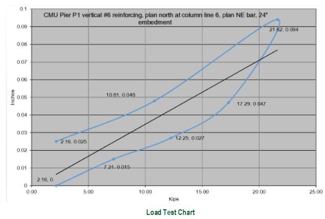
Performing the test, the tensile load is applied in increments, and the axial deflection of the test member is recorded at each increment. At the maximum load the engineer-of-record has specified, the load may be held for a few minutes to measure the “creep,” or the amount of additional deflection the test member exhibits at the maximum load, of the test member. The results of the test are graphed as a function of the load applied and the deflection exhibited.
Generally, the most common form of failure observed in the test is results from poor preparation and installation of the test member. If the hole is not properly cleaned prior to installation, the epoxy will bond to the dust and debris in the hole rather than achieving intimate bond with the concrete. This test is most effective in finding issues with the installation process. Proper installation and observation, which includes continuous special inspections of the installation process, is critical in maintaining the quality of installation.

