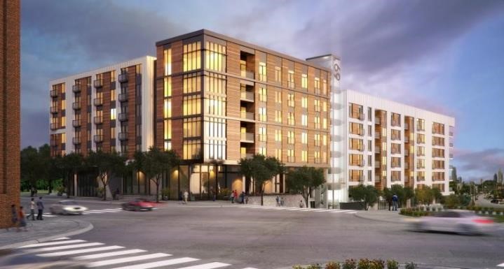
Élan Westside
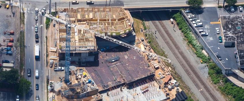
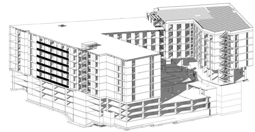
Élan Westside is a multi-family, 197-unit, apartment complex located at the corner of Fourteenth Street and Howell Mill Road in Atlanta, Georgia. The developer of the project is Greystar, headquartered in Charleston, South Carolina. The construction of the 10-level mixed-use building consisted of concrete slabs-on-grade, elevated post-tensioned concrete slabs, wood framing, cold-formed metal framing, epicore composite slab system, structural steel framing, masonry construction, and exterior-insulated finishing system finishes.
Geo-Hydro Engineers, under direct contract with Greystar, provided geotechnical engineering, special inspections, and construction materials testing. The highlights of the project were the varying foundation support systems which included rock, crushed stone, lean concrete, vibro-piers, Micropiles, and mass-graded aggregate base placement. Another special challenge was integration of foundation support systems with the large Mechanically Stabilized Earth (MSE) wall.
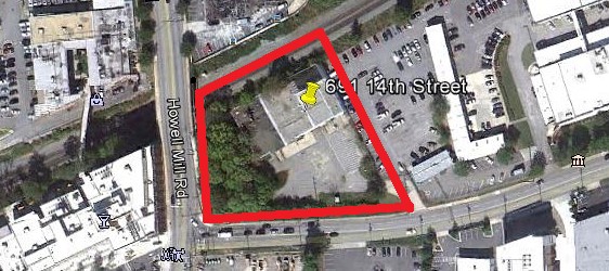
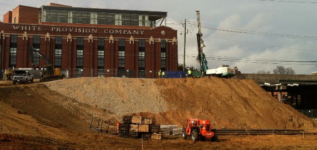
Site conditions prior to construction were an existing building with parking lot.
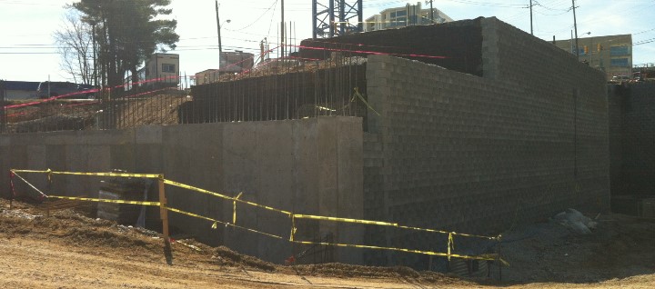
The concrete from the existing building was crushed onsite and later used for backfill along Howell Mill to provide access to install the Soldier Pile and Lagging Wall (Hayward Baker). The soldier pile and lagging wall is approximately 99 feet in length, 30 feet in height and was used to support Howell Mill Road when excavation to place for the storm water tie-in approximately 35 feet below as well as provide future access for the City of Atlanta if maintenance is needed.
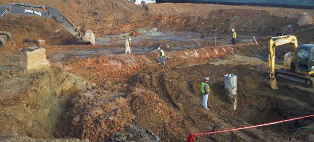
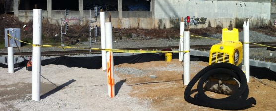
During the excavation of the parking deck groundwater was encountered approximately 8 feet above the lowest elevation of the deck. Dewatering the low areas consisted of sump pits utilizing corrugated pipe and #57 stone. Alluvial soils and an existing City of Atlanta combined sewer built from stacked brick crossed the middle of the site. Both were removed and replaced with onsite soils.
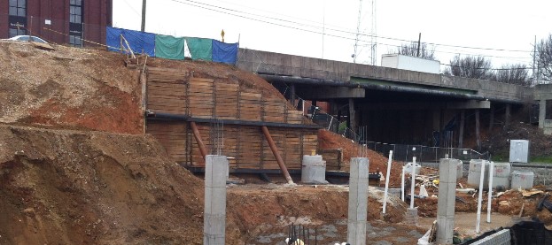
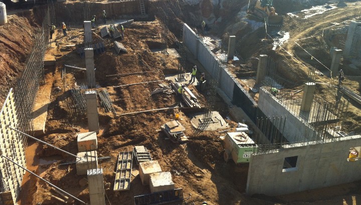
Micropiles (Hayward Baker) were used to support the stair tower for Building #2 due to its proximity to the MSE wall. The micropiles consisted of 1 ½ inch dywidag bars and extended from elevation 924 to 966. Grouting around the annular space between the bars and casing completed the piles. The concrete columns in close proximity to the MSE wall are bearing on rock at elevation 924, and then the columns were constructed in sections to reach elevation 966 as backfill was placed for the MSE wall.
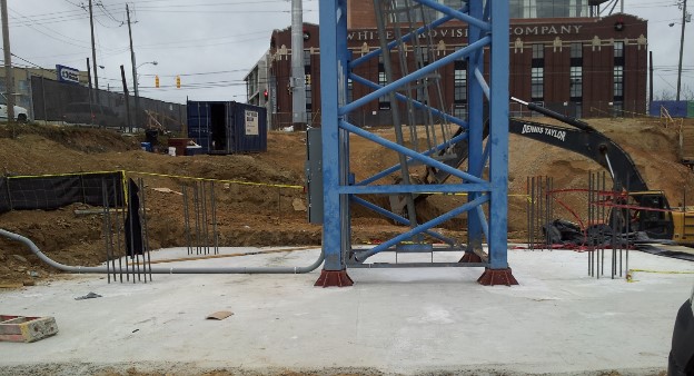
The site consisted of sloping rock from the higher elevation of 934 near 14th Street to the lower elevation of 918. The Tower Crane Foundation with integrated concrete building columns bears on solid rock. Lean concrete was used to level the sloping rock surface before structural concrete was placed in the 40 foot by 40 foot bearing area.
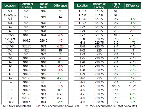
The following tables contain the elevation data we obtained during pneumatic percussion drilling for approximate top of rock elevation and its relation to the approximate design bearing elevation. The numbers colored red indicated where blasting of rock was required to reach the lowest footing bearing elevations.
For this project we utilized the services of GeoWave Solutions to perform the pre- and post-blast surveys and blast vibration monitoring. The following is a list of structures for the pre-blast and post-blast surveys.
- Barking Hound Village - 720 14th Street NW, Atlanta, GA 30318 (full survey).
- Uncle Bob's Self Storage - 680 14th Street NW, Atlanta, GA 30318 (exterior survey).
- Massell Dental Clinic - 700 14th Street NW, Atlanta GA 30318 (exterior survey).
- City of Atlanta Department of Watershed Management - 667 14th Street NW, Atlanta, GA 30318 (full survey western most building and trailer).
- Room and Board Etc. - 1170 Howell Mill Road, Atlanta, GA30318 (exterior leading edge).
- West Side Urban Market and leading edge parking deck wall - N/A Howell Mill Road, Atlanta, GA 30318 (exterior leading edge).
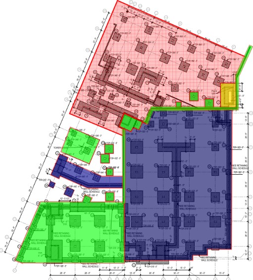
The footing design called for an allowable bearing pressure of 5,000 psf. In order to achieve the design bearing pressure the building is supported using the following methods:
- Aggregate piers (Vibro-Piers) were utilized for foundation support within the parking deck and between lines 14 to 28. The number, depth, and configuration of aggregate piers were determined by the design-build company (Hayward Baker)
- The stair footings at line J are supported by Micropiles designed by Hayward Baker.
- Footings at line 1 to 4 from A to E; N, O, and P on line 13; bear on partially weathered rock, graded aggregate base stone, and lean concrete.
- The planned aggregate piers, located between lines 18 to 24 and K to P, were replaced with a mass fill of graded crushed concrete base stone.
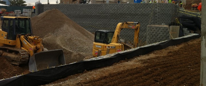
The biggest challenge on the project was the construction of the MSE Wall and Gabion Wall. The MSE Wall measured 350 feet in length and ranged from 32 to 42 feet in height and the Gabion Wall measured 50 feet in length and 28 feet in height. The challenge was the onsite soils were fine grained and not acceptable for the reinforcement backfill zone. We recommended altering the properties of the onsite soils by mixing them with the crushed concrete on site and hauling in crushed concrete graded aggregate. During mixing and wall construction we obtained random soil samples for laboratory testing and performed density testing for compliance with the design parameters.
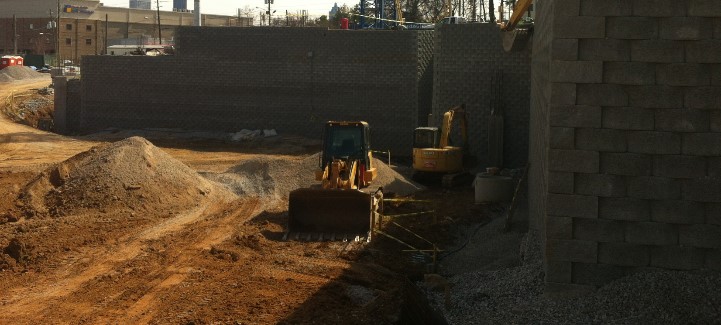
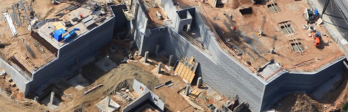
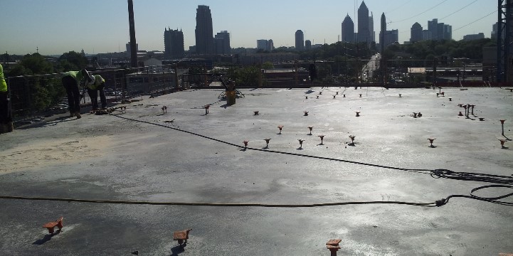
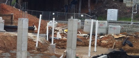
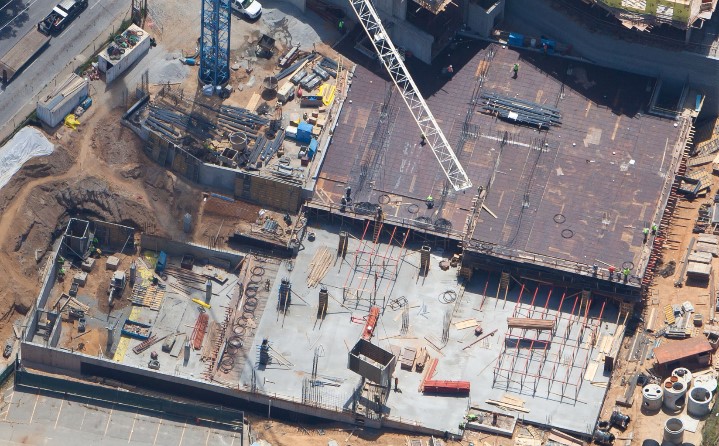
Once the MSE Wall was completed installation of the footing and columns continued within the parking deck and a portion of the building. The parking deck consisted of 5 levels of elevated post-tensioned cast-in-place concrete, part of the building consisted of 6 stories of metal studs with Epicore deck, and part of the building consisted an elevated post-tensioned cast-in-place podium slab then 5 stories of wood construction.
During footing and column construction we observed reinforcing steel placement and sampled and tested concrete in the field and laboratory. During elevated post-tensioned concrete construction we observed reinforcing steel placement, post tension cable alignment and quantity, sampled and tested concrete in the field and laboratory, and recorded elongation records.
The anchor bolts for the wood construction were install prior to concrete placement to avoid conflicts with the post tension cables. During wood construction we periodically checked tie down locations, wood type, and nail and screw spacing.